
Model analysis
Cut it
 Function description
Cut out a 3D model within the scene to see the internal structure. It supports X, Y, and Z multi-directional cutting, and can dynamically simulate the model cutting process and display the results according to the parameters such as cutting depth and playback time interval set by the user.
 Operating instructions
1. Go to the SceneViewer view, click the "Analysis  " function on the right toolbar, and switch to the "Cutting" panel:
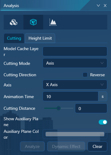
2. Select the model cache layer, here you can list all the layers in "Model Cache Layer", and you can select all or part of the layers for analysis.
3. Set the Cutting Parameter Information:
[Cutting method]: The following three ways:
Axis: The model can be cut according to the X/Y/Z axis direction.
- Axis: set the direction of the coordinate axis;
- Animation Time: When using Dynamic Effects, automatic cutting takes time.
- Cutting Distance: set the position of the sectioning surface, and the position of the sectioning surface can be adjusted by dragging;
Draw Cutting Plane: Draw a line in the scene view interactively, which forms a plane, which is the section.
Draw Clipping Volume: Draw a polygon area interactively in the scene view and set the minimum/maximum elevation range, which can cut the content of the range.
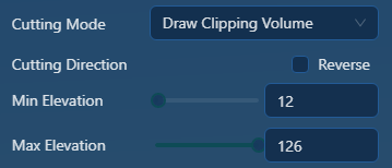
[Cutting Direction]: When the reverse direction is checked, the cutting direction is changed.
[Show Auxiliary Plane]: When enabled, the cut-out auxiliary surface can be displayed and its color information can be adjusted.
4. Click "Analyze" to perform a slice analysis in the scene view.
Tips:
When cutting and analyzing, there is no edge banding by default. You can turn on "Fill Clip" in the "Layer Manager" of the "Layer Attribute" of the "Layer Management" . When opened, edge banding is performed when cutting.
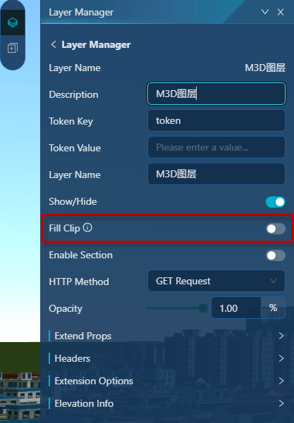
5. When the cutting method is "Axis", click "Dynamic Effect" to dynamically cut the model.
6. Click "Clear" to clear the section analysis effect.
Height limit
Function description
Height limit analysis, through mouse interaction, select the area to be analyzed, and according to the height control height set by the user, the model in the area outside the height control height is identified (color) to display the super-tall building.
Height control analysis is usually used to evaluate the height of urban buildings in urban planning scenarios, and the area beyond the height control line will be highlighted.
Operating instructions
1. Go to the SceneViewer view, click the "Analysis " function on the right toolbar, and switch to the "Height Limit" panel:
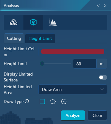
2. Set Parameter Information:
- [Height Limit Color]: Used to set the color of the model that exceeds the height control height.
- [Height Limit]: The maximum height of the Z direction analysis when setting the height control analysis.
- [Display Limited Surface]: Whether to turn on to display the height control plane, if turned on, the height control surface will be displayed. By default, it is not on.
- [Height Limited Area]: The following two methods are supported:
- Draw Area: You can interactively draw rectangles/polygons/circles as analysis areas in the scene view.
- Input Area: Set the center longitude/latitude coordinates and radius values as the analysis area.
3. Click Analyze to draw the analysis area interactively in the scene view to perform height limit analysis.
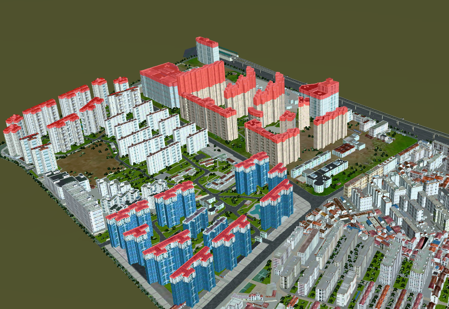
4. Click "Clear" to clear the height limit analysis effect.